4:1 balanced
to unbalanced balun
by SV3ORA
The 4:1 balanced to unbalanced balun is an RF transformer with an important use:
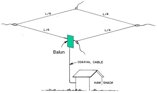
The use of this balun is important in cases where driving a balanced antenna is needed, with a different impedance unbalanced line, such as the coaxial cable. The balun has a transformation ratio of 4:1. This means that a 200 ohm balanced antenna, will be matched to a standard 50 ohm coaxial cable. This balun is for example suitable for large loop antennas, that have an impedance of about 200 ohms, if they need to be fed with a standard 50 ohm coaxial cables.
I have seen cases where a balanced antenna can be driven with a coaxial cable directly, without the use of a transformer. This is fine for transmitting, as long as you do not care to lose radiating power and you have an antenna tuner back in your rig, to eliminate the SWR. For receiving this is fine as well, if you have an RF preamplifier between the antenna and the rig, which is almost always the case.
However my approach is that, in an efficient low loss system, where you do not want to lose any power (such as QRP rigs) the 4:1 balanced to unbalanced balun must be used. Impedance matching of the antenna to the coaxial line, ensures maximum power transfer and elimination of SWR due to impedance mismatch, in both directions, transmit and receive.
The balun I made, comes from the Amidon kit book. It uses an FT-240 toroidal core. Please see the next picture for details of how to build it.
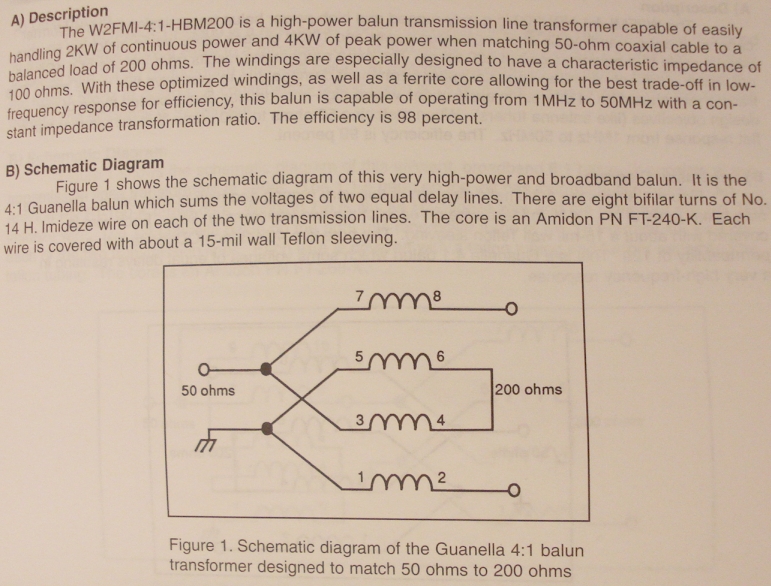
Schematic diagram and information about the transformer.
One thing to make clear, is that the transformer is composed of two sections (transmission lines). Each section has 8 bifilar turns. Windings 7-8 and 5-6 compose the first bifilar winding and are wound on one half of the toroidal core. Windings 3-4 and 1-2 compose the second bifilar winding and are wound on the other half.
Please inspect the picture below, to see details of how to make it. Note the polarity (phase) of the windings, beginning from the coaxial connector. An other way to think of it, is as a 16 bifilar turns transformer, with a tap on the connector side, at 8 turns.
Mark the winding ends with a marker, prior to soldering. Then you know which winding refers to which number, so that you will be able to solder them correctly.

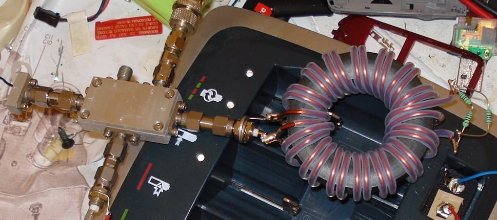
Picture of the transformer
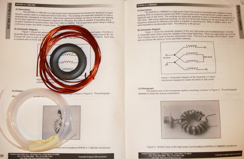
All the components needed
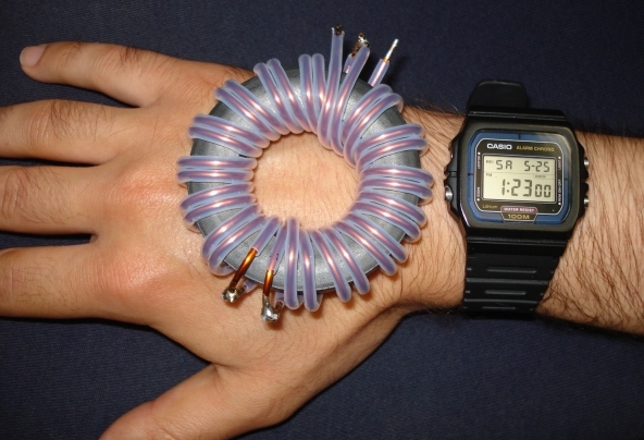
The built transformer
You may notice that some of the windings in the built transformer ends, are overlapping. This is due to the very large diameter wire used. You may use a bit thinner wire to avoid this, without significant degradation in the maximum handling power. However this small overlapping at the ends, does not seem to affect impedance matching.
Measuring the impedance of the transformer
After making the transformer It is time to measure it, to verify that it works as it should. Verifying impedance was done with my impedance bridge in conjunction with my wideband VFO. A 200 ohm resistor was connected between the balanced terminals of the transformer. At the unbalanced end, a 50 ohm SMA connector was used to connect the transformer to the bridge. The VFO was tuned from about 250KHz to 30MHz. For the 6m band, I used a small 45-55MHz handheld transmitter as a generator.
The transformer 50 ohm input port, seems to closely match the equivalent reference 50 ohm resistor at all frequencies mentioned above. Success! To verify that this works for sure, I altered the value of the 200 ohm resistor. The voltage on the D port of the bridge greatly negatively increased, which indicates a mismatched transformer load (antenna).